Powering up OBI
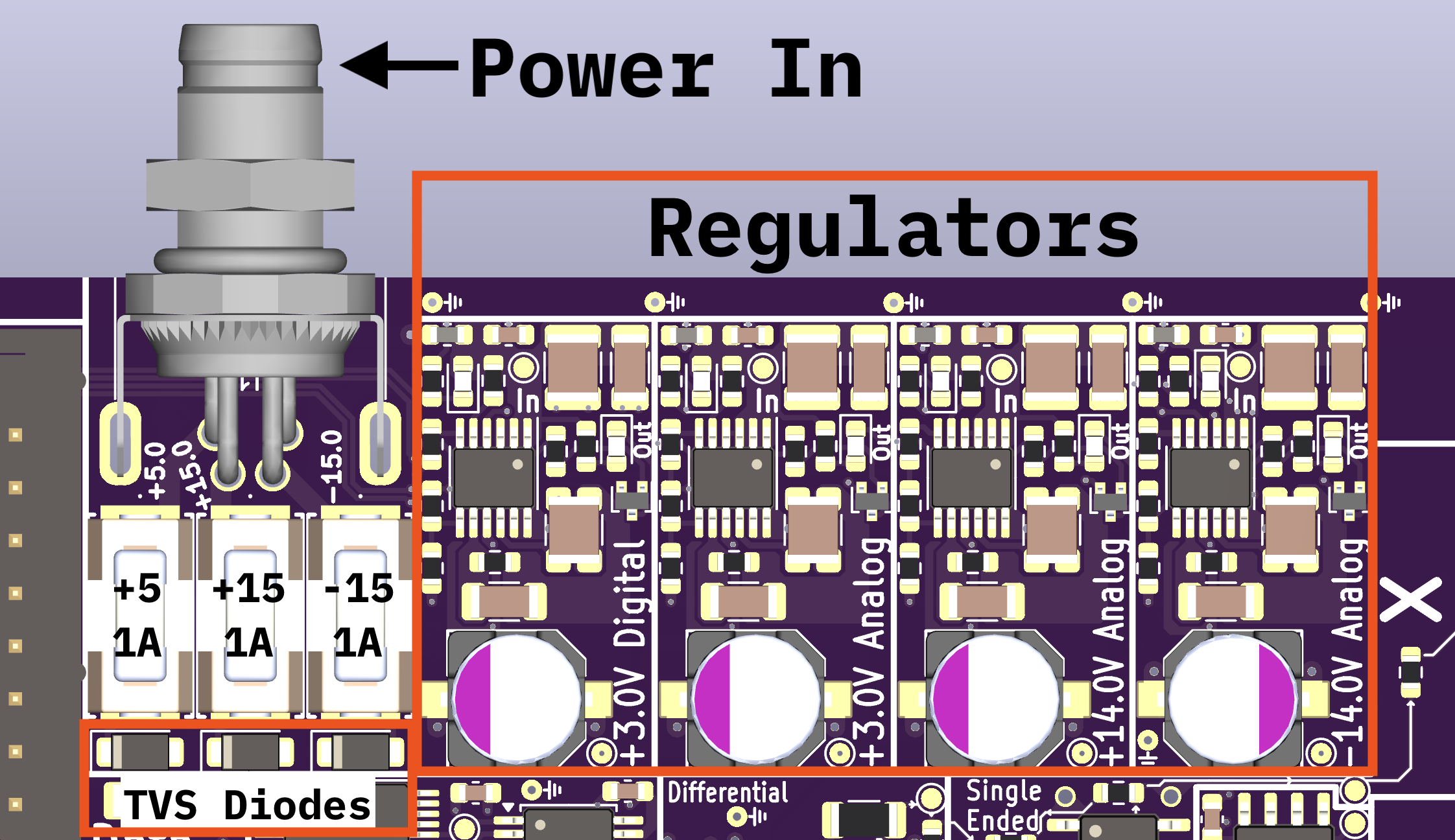
The Open Beam Interface takes a +5V, +15V, and -15V input. Using its onboard regulators, the +5V supply is regulated to a Digital +3.3 rail and an Analog +3.3 rail. The +15V and -15V inputs are regulated to +14V and -14V rails, respectively.

Fuses and Reverse Polarity Protection
Each of the input rails goes through a 1A fuse. The 1A SMD fuse (Littelfuse 0453001.MR) is held in a fuse holder and is interchangeable without soldering.
After the fuse, there is a Littelfuse SMF-20A TVS diode serving as both overvoltage protection and reverse polarity protection. If the voltage on a power rail is reversed, the TVS diode will shunt enough current to ground to blow the fuse. If the voltage on a power rail is of the correct polarity, but exceeds ~20V, the diode will begin to conduct, and depending on the nature of the power supply it’s connected to, may blow the fuse.
If the power supply itself is current limited below 1A, the reverse polarity protection diode may not conduct enough current to blow the fuse.
Power Connector
The input power connector soldered to the PCB is a four-pin Nano M8 connector with the following pinout:
Pin |
Voltage |
|---|---|
3 |
+5V |
1 |
Gnd |
2 |
-15V |
4 |
+15V |
Note that M8 connector pins are NOT numbered sequentially.
Mating Connector
Any 4-socket Nano M8 connector will mate with the onboard power connector. We find the screw terminal M8 connectors from Binder to be of excellent quality. We recommend using crimp ferrules when assembling the connector.
Sourcing Power From Within An Electron Microscope
Depending on the configuration of your microscope, it may be sensitive to ground loops or other types of interference that can happen when connecting multiple power supply sources or multiple grounds together. To avoid this, we frequently source power for OBI from the microscope’s internal power supply rails. Most microscopes will have a +5 and +-15V rail meant for optics, detectors, and imaging. It is frequently possible to construct a cable to tap into these rails via an existing power distribution connector.

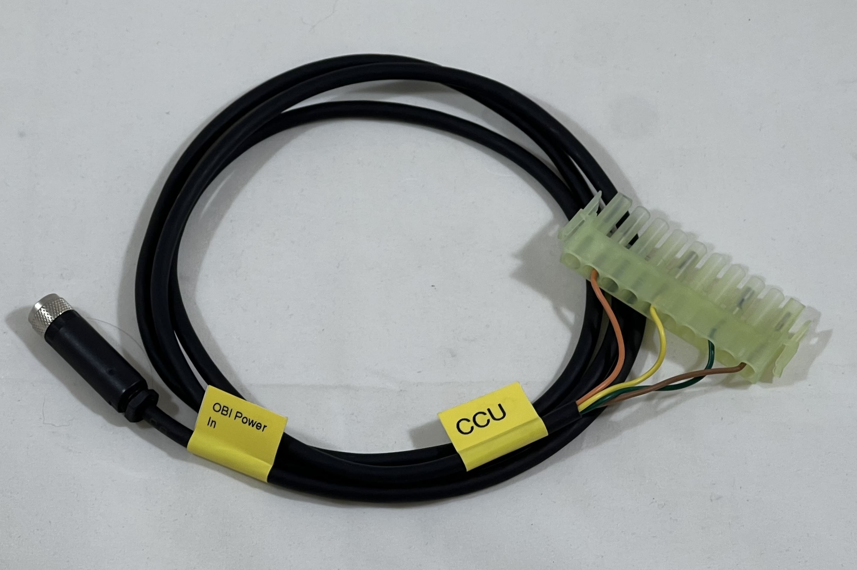
Example: FEI CCU/DDB to OBI Power Cable
Voltage |
Mate-N-Lok Pin |
OBI Power In Pin |
|---|---|---|
+5V |
1 or 2 |
3 |
Gnd |
3, 4, 7, or 8 |
1 |
-15V |
5 or 6 |
2 |
+15V |
9 or 10 |
4 |